Challenging Projects
Very oftern tunnels are naturally supported by the mountains and rocks they are bored through. At Obayashi, we are constantly striving to develop tunneling technology by proactively introducing the use of Artificial Intelligence (AI) and Information Communication Technology (ICT). We have leveraged our years of research and development efforts in traditional engineering, hydrology, geology and rock mechanics to develop new technology. Let us introduce you to some of our most challenging projects in Japan that showcases our various technologies and knowledge.
Challenging project ❶
Japan's first water-sealed underground LPG storage tank
Namikata National LPG Stockpiling Base
- Project name
- Namikata base butane storage tank construction
- Owner
- Japan Oil, Gas and Metals National Corporation
- Constructor
- Obayashi Corporation, Tobishima Corporation, Konoike Construction Corporation Joint Venture
- Construction period
- April 2003 - March 2013
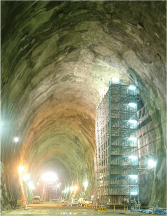
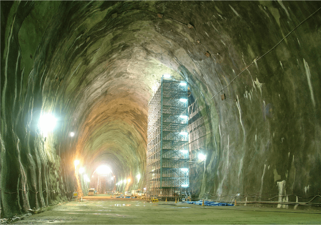
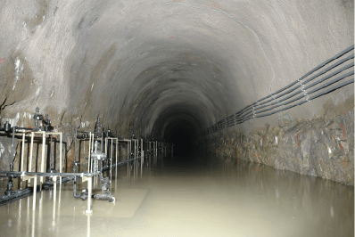
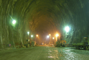
The Namikata National LPG Stockpiling Base in Imabari City, Ehime Prefecture,
is the first water-sealed underground rock cavern (stockpiling base) in Japan to store Liquefied Petroleum Gas (LPG).
The cavern is 26 meters (85 feet) wide and 30 meters (100 feet) high.
Its cross-sectional area is 655 square meters (7,050 square feet) and the storage capacity is the largest in the world.
To ensure the water sealing function and the stability of the cavern about 150m (500 ft) below ground,
the excavation was carried out with continuous observation and analysis.
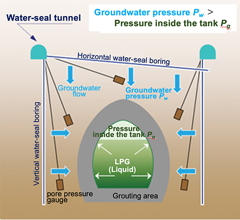
What is water-sealed underground stockpiling?
Water-sealed underground stockpiling is a method of storing liquefied petroleum gas at room temperature and high pressure by utilizing the ground water pressure around the storage tank without covering the walls with concrete or steel. Since the groundwater pressure towards the storage tank is higher than the pressure inside the tank, the stored materials are contained within.
The construction of this water-sealed underground LPG storage tank was the first of its kind in Japan. Thus, Obayashi formed a technical alliance with Geostock, a French company that is a global leader in the design and construction management of LPG underground storage tanks. Hydrogeological engineers from Geostock were dispatched to the construction site for two years to analyze the hydrogeological conditions and evaluate the effectiveness of water sealing methods.
Construction of complex underground space
Namikata National LPG Stockpiling Base has a very complex structure with many tunnels, including working tunnels and water-seal tunnels, in addition to the main underground LPG storage tank.
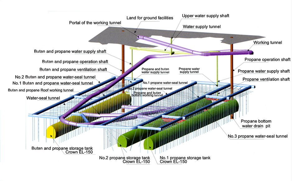
From the website of Namikata Terminal Co., LTD.
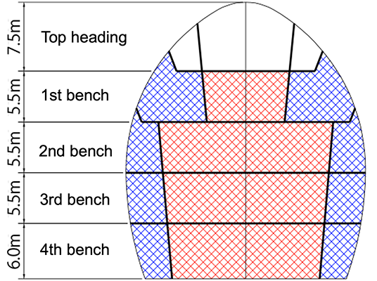
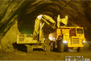
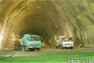
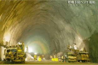
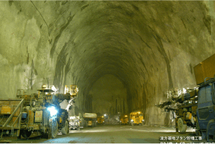
In particular, the storage tank cavern had to be excavated by dividing it into a top heading and four benches, which made construction extremely difficult.
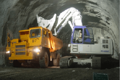
Obtaining geological information
For the excavation of the main storage tank, obtaining details of its geology such as fractures was crucial to ensure the water sealing effectiveness and the stability of the cavern.
Securing the water seal
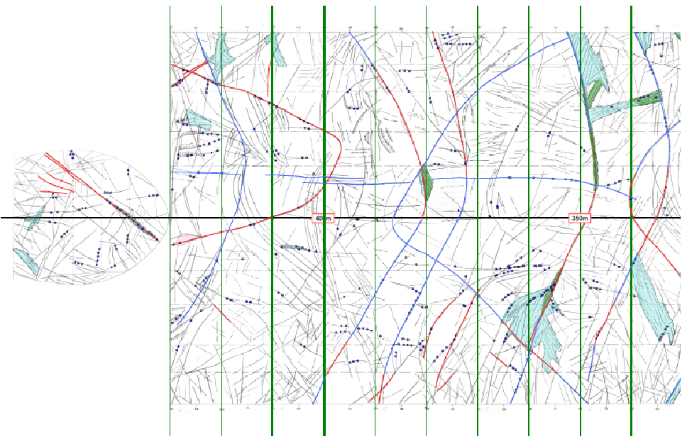
Prediction of groundwater flow by identifying fracture strike, dip and continuity

Determine the location and direction of water seal boring and water cut-off grouting to ensure water sealing effectiveness
Ensuring cavern stability
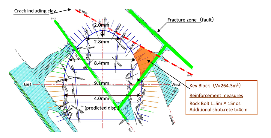
Identify unstable rock blocks by examining the location of cracks and inclusions of clay and other materials
Develop countermeasures such as reinforcement of support to ensure cavern stability
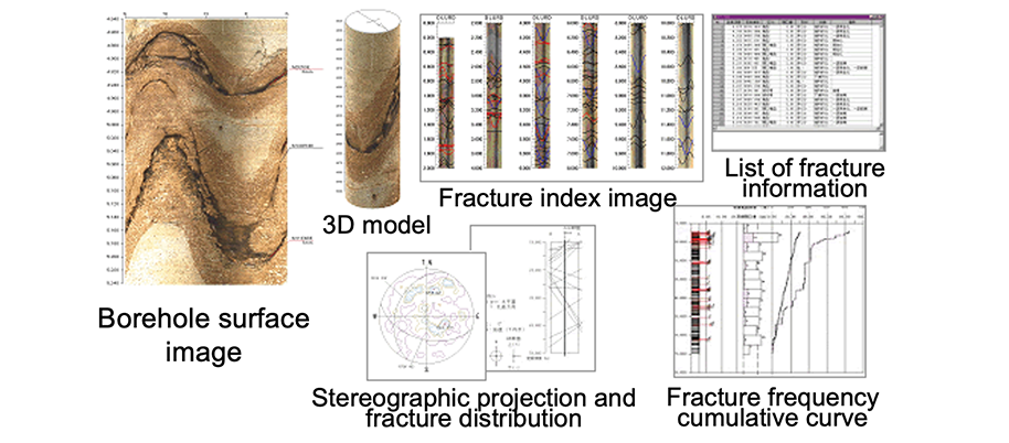
In order to obtain geological information such as fractures, detailed maps of fracture properties were prepared from visual observation of tunnel face, observation of boring cores, and the analysis of bore surface images of water seal boreholes and grout holes. All the data was collected and analyzed by geological experts. The maps were continuously updated to improve the accuracy of the water sealing effectiveness and cavern stability.
Securing the water sealing function
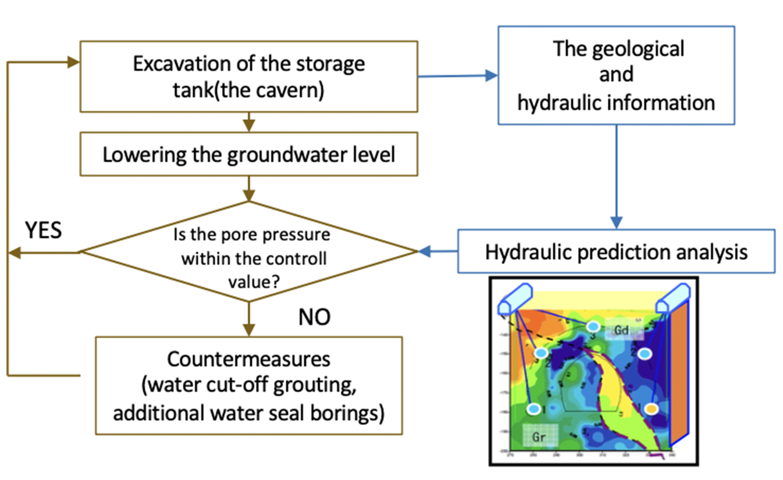
During excavation, a large amount of water inflow may occur, lowering the groundwater level, and unsaturated areas (soil containing air) may develop around the cavern, decreasing the water seal effectiveness. To avoid this danger, it is necessary to maintain the groundwater above the required level and to prevent the formation of unsaturated zones in the rock around the cavern. For that purpose, information-based construction was used to control groundwater behavior.
Pore pressure was monitored by sensors at 42 locations in 9 cross sections during excavation of the tank, and based on the geological and hydraulic information obtained, hydraulic prediction analysis was carried out continuously. When a drop in the pressure was observed, water cut-off grouting and additional water seal borings measures were applied.
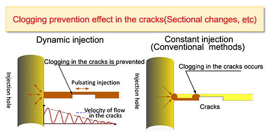
There was a concern that standard water cut-off grouting procedures may not be effective enough due to clogging of the injection material in the fracture. As a countermeasure, a dynamic grouting system was adopted.
The system prevents clogging of the grout in the cracks by injecting the grout with a pulsating injection pressure instead of a constant injection pressure. With this technique, a low permeability zone of less than 1Lu (10-5cm/sec) was formed for 10m around the storage tank.
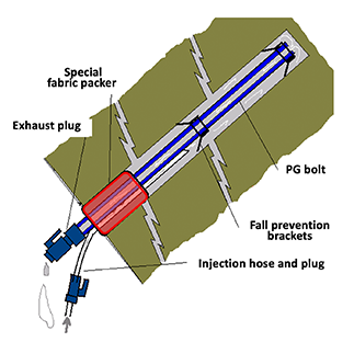
Rock bolts 4m to 7m long are used to support the storage tank bedrock, but if there is water inflow through the rock bolt holes where the bolts are embedded, the water pressure will decrease significantly. Even a small amount of water at a rate of 1 L/min can affect the water pressure.
To prevent this situation, PG bolts with a special fabric packer were used in the hole openings. Since PG bolts are difficult to inject in areas with a large amount of water inflow, they were only used under water inflow conditions of 0.5 L/min or less, and water cut-off grout was used when the amount was 0.5 L/min or more.
Ensuring cavern stability
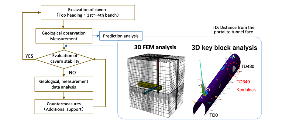
During the excavation, the geology was observed and the displacement and support stresses were measured constantly to check the stability of the cavern. Also, the stability of the support and surrounding rock masses was confirmed by 3D FEM analysis, and the emergence of unstable rock masses was predicted by 3D key block analysis, so that countermeasures were taken as soon as they were needed.
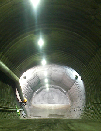
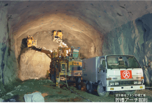
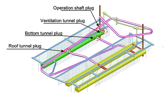
Concrete plugs, the key to airtightness
Since the storage tank contains petroleum gas, its connection points to the tunnels and vertical shafts must be plugged after the pipes are installed. These connection points were plugged using reinforced concrete and required to be airtight to prevent any leaks.
From “Evaluating the Ground Relaxation from Excavation of the Namikata LPG Storage Cavern Using AE Method,” Proceedings of the 39th Symposium on Rock Mechanics, lecture no. 26
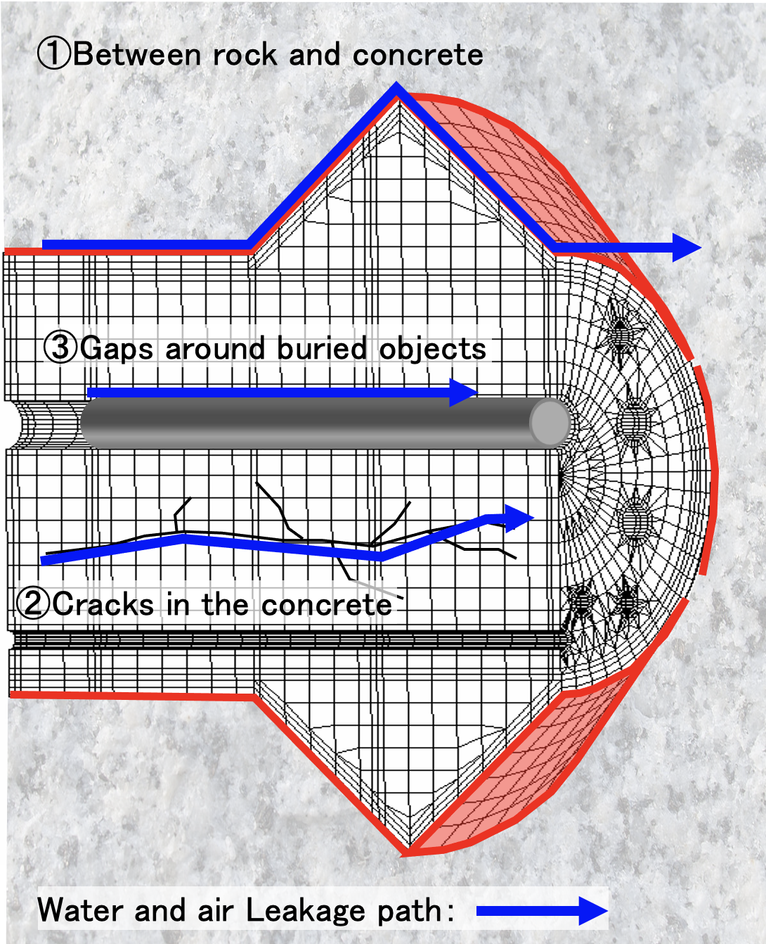
Petroleum gas leaks occur mainly at the following three locations.
(1) Between rock and concrete
(2) Cracks in the concrete
(3) Gaps around buried objects
The following measures were taken to address these issues.
・Voidless filling and prevention of thermal cracking with self-compacting concrete using low exothermic cement and expansion agent
・Suppression of thermal cracking by cooling
・Closure of the gap between rock and concrete by contact grouting
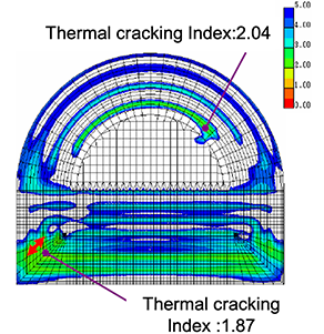
by thermal stress analysis
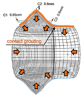
caused by cooling
Operation of Japan's first water-sealed
underground storage tank
To store the petroleum gas, the storage tank needs to be airtight. An airtightness test (based on Article 45, a part of the Regulation on Inspection of Specific Equipment of the High Pressure Gas Safety Act) was conducted by filling the cavern with compressed air and confirming there was no loss of pressure due to leaks.
Using the gas state equation PV=nRT, the test confirmed that the pressure P did not decrease. Temperature measurement with an accuracy of 0.01℃ was also conducted and included in the equation to exclude the effect of temperature T change. These procedures allowed us to accurately detect even the slightest change in pressure P. In addition, to check for air leaks from the submerged piping shafts, video surveillance was conducted with a web camera for 72 hours.
There was no loss of pressure or leakage of air bubbles, so the tank passed the airtightness test, ready to store the petroleum gas.
The construction of the Namikata Stockpiling Base took about 10 years and was completed in March 2013. The storage of petroleum gas was completed in December 2016, and currently about 450,000 tons of petroleum gas are stored there.
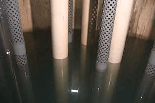
(no air bubbles detected)

Challenging project ❷
Excavation of extremely squeezing ground with the multiple layer support method
Hokuriku Shinkansen Iiyama Tunnel
(Itakura construction section)
- Project name
- Hokuriku Shinkansen, Iiyama Tunnel (Itakura section)
- Owner
- Japan Railway Construction, Transport and Technology Agency
- Constructor
- Obayashi / Daiho / Matsumura-Gumi /Tanaka-Sangyou Joint Venture
- Construction period
- March 2000 - September 2005
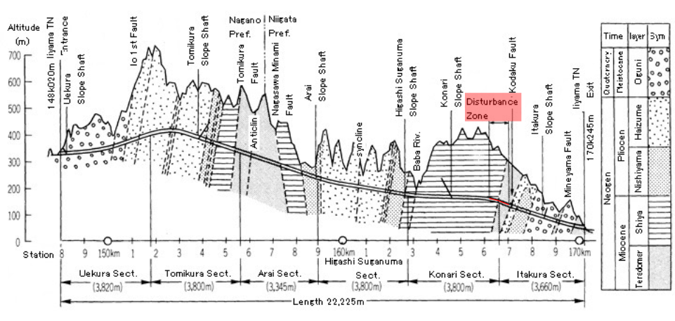
The Iiyama Tunnel of the Hokuriku Shinkansen is a 22.251 km long tunnel
that runs from Iiyama City in Nagano Prefecture to Itakura Town in Niigata Prefecture.
Obayashi Corporation JV was in charge of the Itakura section (3,660 m long) at the exit on the Niigata Prefecture side.
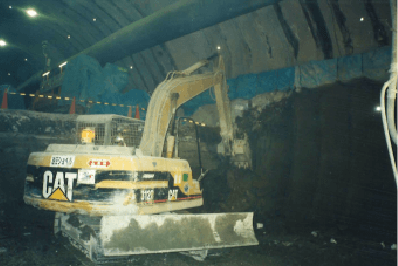
Around 500m in, on the Nagano Prefecture side,
squeezing ground with enormous pressure was encountered,
so multiple layer support and early invert closure measures put into place.
However, the tunnel excavation was still difficult and required multiple layer support structures
with higher bearing capacity and earlier section closure to penetrate through the unprecedentedly unstable ground.
What is squeezing and swelling ground?
Squeezing and swelling ground occurs when the ground deforms during tunnel construction, causing expansion into the inner section of the tunnel. This type of ground often consists of mudstone, shale, tuff, serpentine or solfataric clay.
When tunnels are constructed in squeezing and swelling ground, high ground pressure acts on the support and lining, causing the face to push out and the bottom ground to lift up, resulting in heaving and other problems that make tunnel construction and maintenance difficult.
Squeezing and swelling ground is classified according to the following occurrence factors.
Swelling ground Swelling pressure occurs due to the hydroscopic expansion (expansion by water absorption) of clay minerals (e.g., montmorillonite).
Squeezing ground The stress in the surrounding ground increases as the tunnel is excavated and eventually exceeds the strength of the ground, causing the ground to extrude plastically into the inner section of the tunnel.
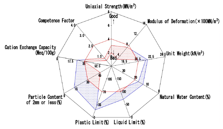
There are various indices to evaluate the expansive nature of the ground, such as montmorillonite content and competence factor. During the construction of the Iiyama Tunnel (Itakura section), the expansibility of the ground was checked using these indices, and it was found that the mechanical properties such as uniaxial strength and modulus of deformation were low, indicating squeezing ground conditions.
Encountering the squeezing pressure
The mudstone layer located on the border between the Itakura and Konari sections of the Iiyama Tunnel is a disturbed zone with a series of fractured fault zones. The overburden is relatively large (140-180m) with low ground strength, defining it as squeezing ground with a low competence factor.
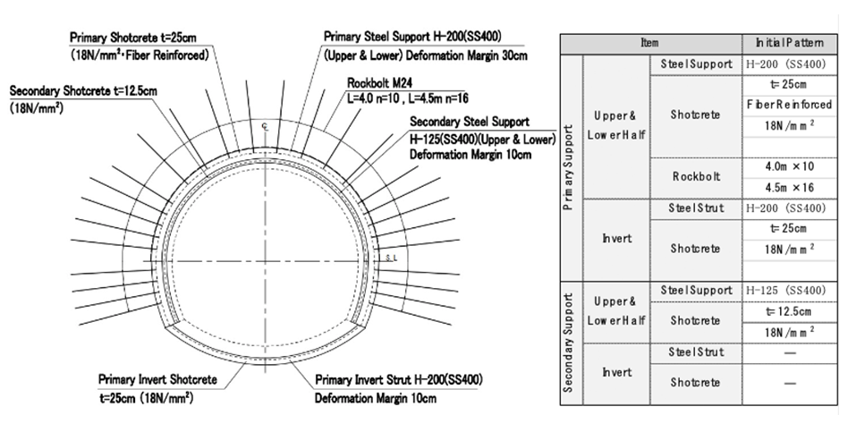
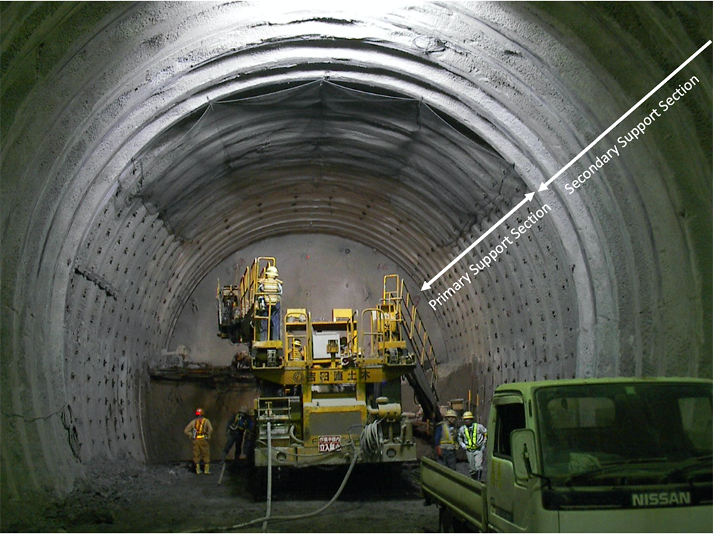
Initially, the short bench cut method was used to excavate the site, but as the ground deteriorated, the inner space displacement increased. The horizontal displacement was more than 200mm and the settlement of the footing was more than 1400mm. Thus, the construction method was changed to the mini-bench cutting method. In addition to the early closure of the cross-section, the multiple layer support method was adopted. This method allows for a certain amount of displacement of the primary support and ensures the integrity of the entire support structure by installing the secondary support on the inside of the primary one.
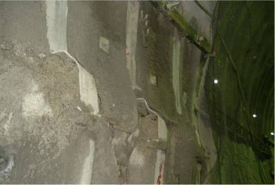
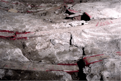
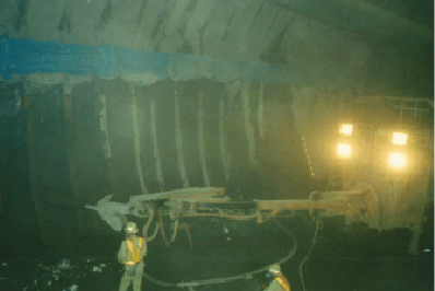
Squeezing pressure beyond anticipation
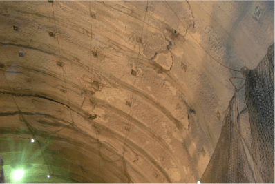
The initial plan was to install the secondary support at a distance of 3.5D (D: tunnel excavation width: 11.65m) from the excavation of the upper half of the tunnel, but before the secondary supports were installed, horizontal displacement of the upper half exceeded 300mm, causing damage to the shotcrete and bending the steel supports. Furthermore, the displacement did not stop even after the installation of the secondary supports, leading to the rupture of the invert struts.
In this disturbance zone, the displacement rate of the ground was faster and the squeezing pressure higher than expected, so it was necessary to control the displacement at an earlier stage and to improve the bearing capacity of the entire support.
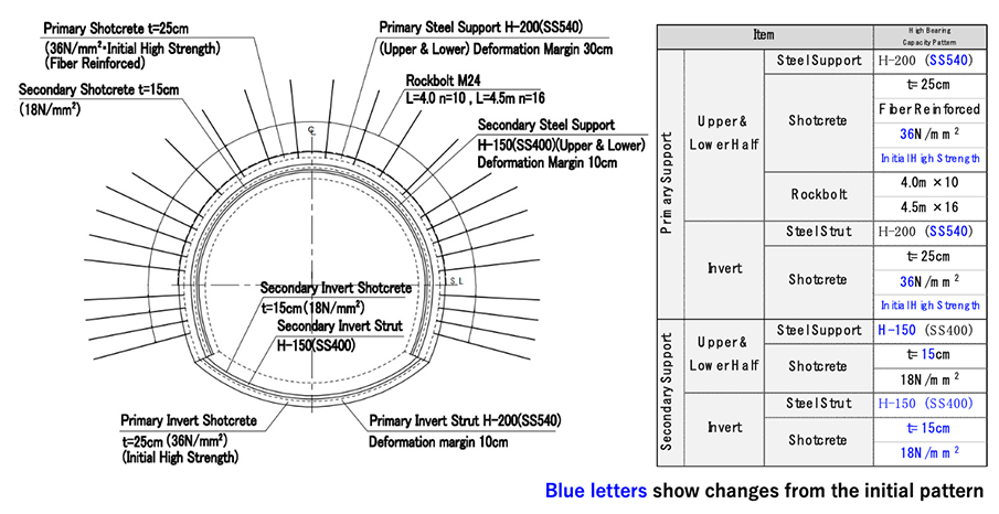
Upgrading of multiple layer support
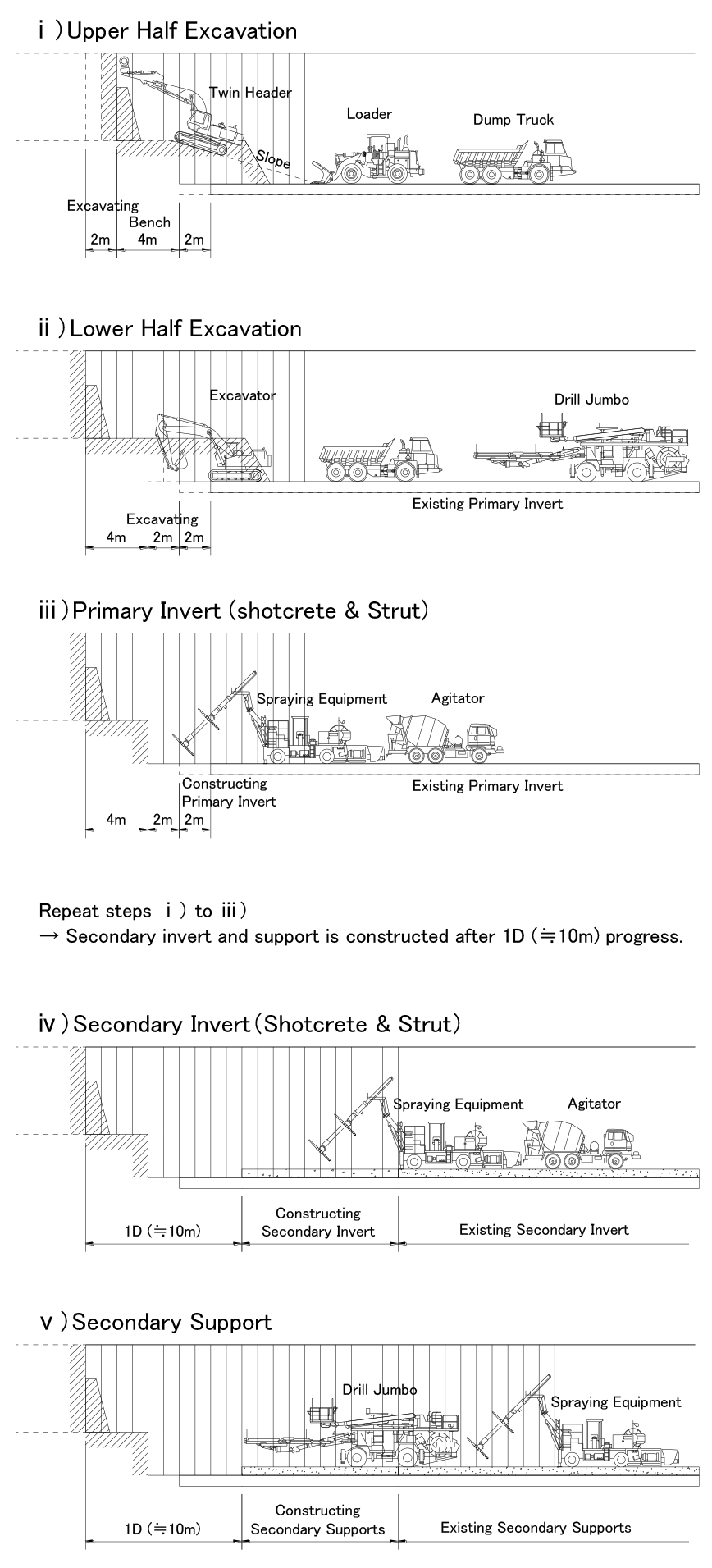
Considering the displacement and damage to the support, the construction method was changed as follows.
・Construct the secondary support at the stage where the top heading is 1 to 2D ahead for early closure.
・Increase the bearing capacity of the primary and secondary support.
As a result of these measures, the displacement of the inner space was reduced to around 200 mm, and no deformation occurred after the installation of the secondary support.
Verifying the effectiveness of multiple layer supports
by ground characteristic curve analysis
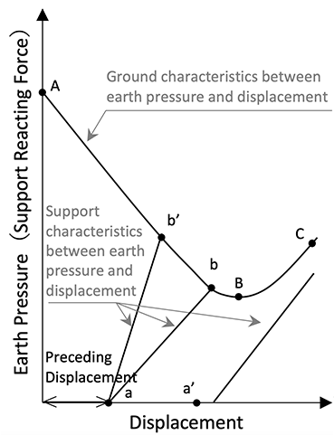
What is a ground characteristic curve? The ground characteristic curve shows the ground behavior during tunnel excavation and the effect of support.
When a displacement occurs in the ground, a corresponding stress also develops. In other words, the load is borne by the ground, and the ground pressure acting on the support is reduced (point A → B). However, if the displacement is too large, the ground will soften and the ground pressure acting on the support will increase (point B →C).
To stabilize the tunnel, the displacement must be kept to the left of point B. Preceding displacement occurs before the installation of support, but after the installation, displacement occurs in the support and the support reaction increases (point a → b). The tunnel stabilizes when the support reaction is balanced by the ground pressure (point b).
Upgrading the support means steepening the slope of the support characteristics in this graph (point a → b'). Strong support reduces the displacement. But if the installation of support is too late (point a'), the ground pressure cannot be supported by the reaction force of the support, and the tunnel will be unstable.
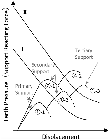
What is the effect of multiple layer support?
In squeezing and swelling ground, the ground pressure is large (I), and the primary support cannot hold the ground pressure (①-1). Therefore, a secondary support is added to hold the ground pressure with the support reaction and to stabilize the tunnel (①-2).
When the ground pressure is greater (II), tertiary support is added (①-3) or the bearing capacity of the multiple layer support is increased (②-1, ②-2).
The latter method was adopted for the Iiyama Tunnel (Itakura section).
From “The multiplied tunnel support system is an effective countermeasure against squeezing ground condition” by Shuzo Kitagawa, Tunnels and Underground, Vol.34, No.2, pp.55-65, 2003
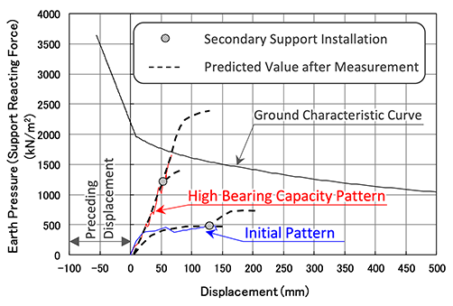
Effectiveness of multiple layer support for the Iiyama Tunnel (Itakura section) Measurements taken at the Iiyama Tunnel (Itakura section) confirmed the effectiveness of the multiple layer support.
The relationship between the support reaction and displacement is calculated using the stress measurement results of shotcrete and steel support, assuming a circular tunnel with hydrostatic ground pressure.
Ground characteristic curves were calculated based on the Hoek-Brown elasto-plasticity theory, with physical properties set based on ground sample tests and examples of similar grounds.
The initial pattern was not able to support the ground pressure due to insufficient bearing capacity, while the high bearing capacity pattern was able to support the tunnel by balancing the ground pressure and support reaction.
By verifying the actual measurement results using the ground characteristic curve, the necessity and effectiveness of the multiple layer support in the Iiyama Tunnel (Itakura section) was confirmed.
With a total length of 22.251 km, the Iiyama Tunnel is the third longest railroad tunnel in Japan (as of 2020). The knowledge gained from the construction of this long tunnel in squeezing ground will be utilized in the tunnel construction in difficult ground.
in the Iiyama Tunnel (Itakura section)
Challenging project ❸
Tunnel construction in unconsolidated ground with high groundwater,
directly under dense residential areas
Construction of Kobe Nagata Tunnel
- Project name
- Tunnel construction of Nagata section (southbound) of Kobe City 2nd Highway Line
- Owner
- Hanshin Expressway Public Corporation (now Hanshin Expressway Co., Ltd.)
- Constructor
- Obayashi Corporation
- Construction period
- February 1996 - October 2002
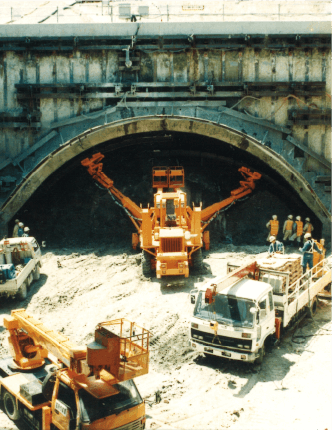
This is the highway tunnel construction in Kobe after the Great Hanshin-Awaji Earthquake.
The site is located directly under a densely populated residential area with many buried utilities such as water and gas lines.
The construction in unconsolidated ground with high groundwater and
a shallow overburden (geology with a lot of sand and gravel) was extremely difficult.
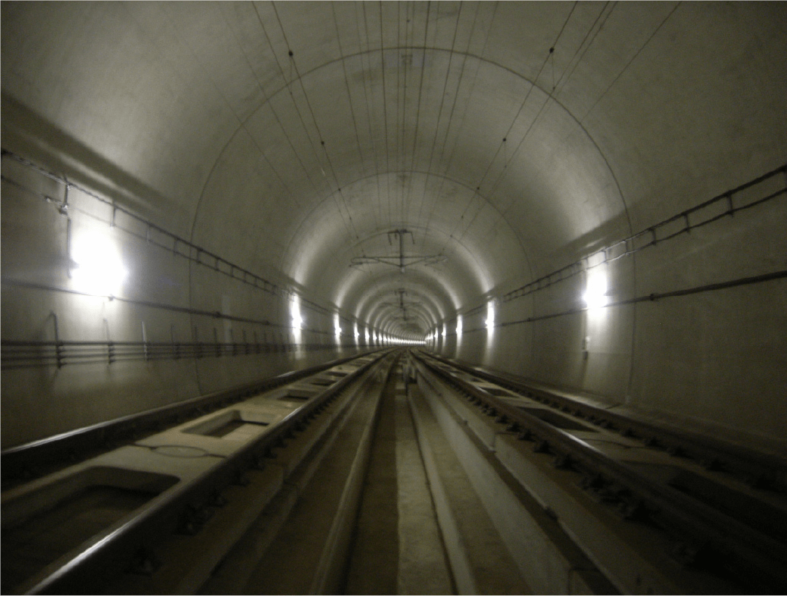
What is the Kobe Nagata Tunnel?
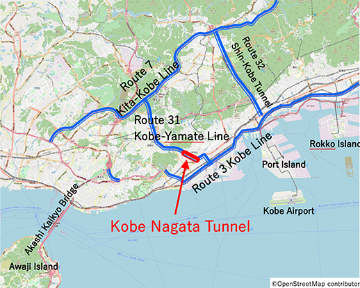
The Kobe Nagata Tunnel is a road tunnel on the Hanshin Expressway Route 31 Kobe-Yamate Line which travels in a south to north direction in western Kobe
The Route 31 Kobe-Yamate Line connects the Route 3 Kobe Line and the Route 7 Kita-Kobe Line, and is about 9.5 km long, of which about 70% is tunnel structure. The Kobe Nagata Tunnel is the most seaward tunnel of the Kobe-Yamanote Line. The 2.1 km-long tunnel consists of northbound and southbound two-lane tubes.
The construction was divided into four sections, and Obayashi was in charge of the Nagata section (southbound), which is on the seaward side of the southbound line.
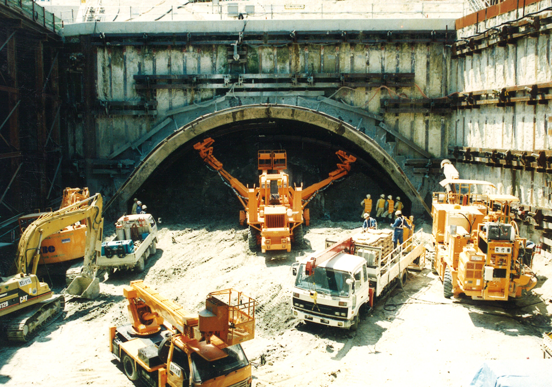
Construction in the midst of post-disaster recovery
Construction began in February 1996, a year after the Great Hanshin-Awaji Earthquake in January 1995. The city of Kobe suffered extensive damage from the disaster, with the collapse of homes and areas cut off from transportation, especially in the Nagata Ward. Since the reconstruction of the city was given priority, some equipment and materials needed for the tunnel work were difficult to procure.
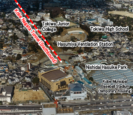
Our temporary material yard was located in Nishidai Hasuike Park. Also located in the park is Kobe Municipal Baseball Stadium where temporary housing units were set up for evacuees.
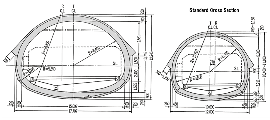
A large cross section tunnel with heavy reinforcement supports
The area 85 meters in from the portal is the widening section for the branch lane at the Nagata entrance / exit. The design is to gradually transition from a large cross section with a maximum excavation width of 19m and a cross sectional area of 186 m2 to a standard cross section with an excavation width of 13-14m and a cross sectional area of 103-115 m2.
With the widespread use of groundwater wells in the surrounding residences and other factors, it was necessary to recover the groundwater levels after the completion of the tunnel. Thus, a watertight tunnel structure with waterproofing membrane around the entire perimeter and a double-reinforced structure was specified.
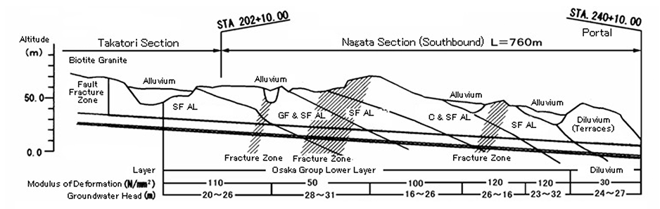
Excavation of the unconsolidated Osaka Group with high groundwater
The tunnel was planned to traverse under mostly residential areas with gently sloping hills that varied in elevation from 10 to 80 meters. The overburden, from the top of the tunnel to the ground surface, was shallow, ranging from 25 to 50 meters (average 35 meters), except for an extremely shallow section (about 12 meters) near the portal.
The geology consisted of the lower Osaka Group of the Quaternary period, which was composed of alternating layers of rudaceous, arenaceous and mucilaginous soils, as well as terraces and alluvium of the late Pleistocene period. The geology of the tunnel area consisted of terrace strata up to about 140 m from the portal, and Osaka Group beyond that. The Osaka Group, with highly consolidated clays, had a deformation modulus of E=50-120N/㎜2 and flowed against the tunnel face.
The rudaceous and mucilaginous soils contained an aquifer that stored a large amount of groundwater at a table elevation 16 to 32 meters above the tunnel.
Suppression of ground surface subsidence
The key to this tunnel construction was to control the subsidence of the ground surface while excavating unconsolidated ground with a shallow overburden and high groundwater level. We also had to avoid damage to structures above and underground utilities.
The following were the four key points.
- ● Impacts on the above ground and underground structures due to shallow overburden and unconsolidated soil
- ● Instability, loosening, and displacement of the crown and face of the tunnel
- ● Co-settlement, loosening and displacement due to insufficient ground bearing capacity of the footing
- ● Destabilization, loosening, and displacement of the lower half of the side wall
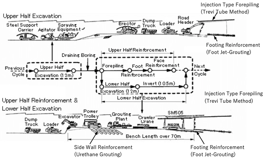
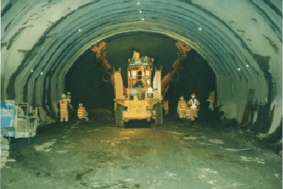
Auxiliary methods to suppress ground surface subsidence
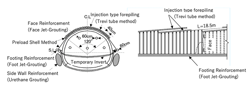
The following auxiliary excavation method was used in this project.
① Injection type forepiling (Trevi tube method)
[Objective]
・Suppression of ground surface subsidence, including advanced settlement in front of the face
・Stability improvement of the crown and face
[Summary]
For the forepiling, Trevi tubes were used, since the same equipment can also be used for high-pressure jetting (face jet-grouting).
By extending the length of one cast-in-place steel pipe from the standard length of 12.5 m to 18.5 m, the production of one shift was extended from 9 m to 12 m, which shortened the construction duration and reduced construction costs.
Based on the ground conditions, overburden and preliminary measurements, the amount of ground surface subsidence that would occur during each subsequent shift was estimated, Then, the steel pipe diameter (114.3 mm or 139.8 mm) and grout agents (urethane and cement milk) were selected for the estimated subsidence.
Preload shell method was used for the support footing. A bag filled with rapid hardening mortar was placed in the gap between the steel support and the ground, allowing for quick transfer of the load from the steel support structure to the ground, thereby suppressing subsidence.
(Trevi tube method)
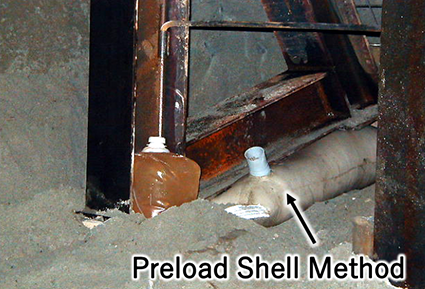
(footing of support)
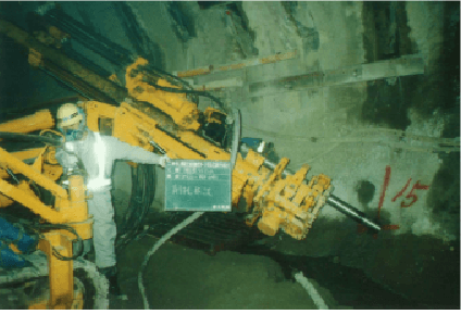
② Reinforcement of the face (face jet-grouting)
[Objective]
・Stability improvement of the face
[Summary]
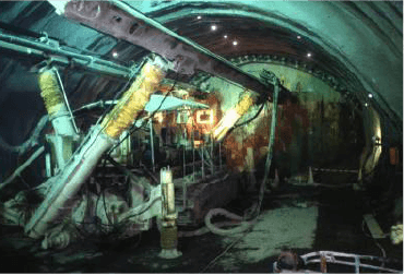
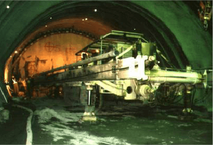
With the face instability due to unconsolidated ground and high groundwater, ground stabilization, in addition to bolt reinforcing, was necessary. So face jet-grouting was selected.
This method is used for forming an improved structure around the drilled area by spraying cement hardener from a high-pressure jet nozzle at the tip of a penetrating and rotating rod. The same machine is used for installing Trevi tubes.
The number and locations for the jet grout was determined based on the ground conditions and face stability. Each application has a target diameter of 600 mm.
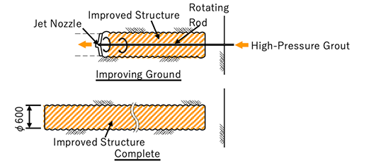
(face jet-grouting)
③ Footing reinforcement (foot jet-grouting)
[Objective]
・To improve the ground bearing capacity at the foot of the steel support structure to prevent foot subsidence.
[Summary]
Foot jet-grouting and the urethane grouting, both proven effective in similar ground, were compared as countermeasures for water inflow. Based on test construction results, the former was selected for having greater improvement results than the latter. The materials and construction method used were the same as face-jet grouting, and the construction position and the casting length were the same as those of forepiling.
④ Reinforcement to the lower half of the side wall
[Objective]
Stabilization of the lower half of the side wall, controlling loosening and ground displacement
[Summary]
Side wall jet-grouting and urethane grouting were considered for these conditions. Based on test construction results, urethane grouting was selected for its workability and ability to ensure side wall stability. Using a general-purpose crawler drill, the side wall reinforcement was placed diagonally forward and downward from the upper half of the wall, with one reinforcement every 2 meters on each side.
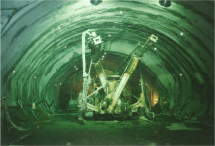
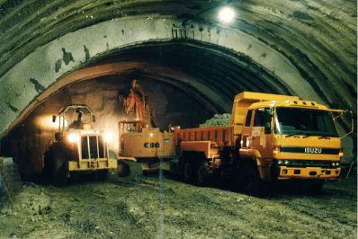
Excavation status
Staring at the top heading and cutting a bench, parallel (translational) excavation was performed alternating between the upper and lower half. The length of the bench was more than 70m to allow space for equipment to install reinforcement measures.
The lower half excavation, waterproof membrane installation, and invert concrete placement, were carried out in parallel with the upper half reinforcement work.
The amount of work for the lower half construction activities per cycle was adjusted to match the cycle time of the reinforcement work in the upper half to avoid unnecessary waiting time.
Conclusion
In April 2001, about four years after the start of excavation, the Nagata section was successfully connected to the Takatoriyama section of the Kobe Nagata Tunnel. The mission to "suppress ground surface subsidence" was achieved without causing any damage to above ground buildings or underground utilities. Solving various issues with technology and ingenuity, we achieved an average monthly advance of 20 meters in the standard section of the tunnel.